Brushed DC Motors
Define supply voltage, speed at load, torque and operating cycle for your equipment.
Explore motor type
MOTOR SELECTION
Search verified configuration data by commutation, construction and operating requirements. Share your equipment task when the required configuration is not listed.
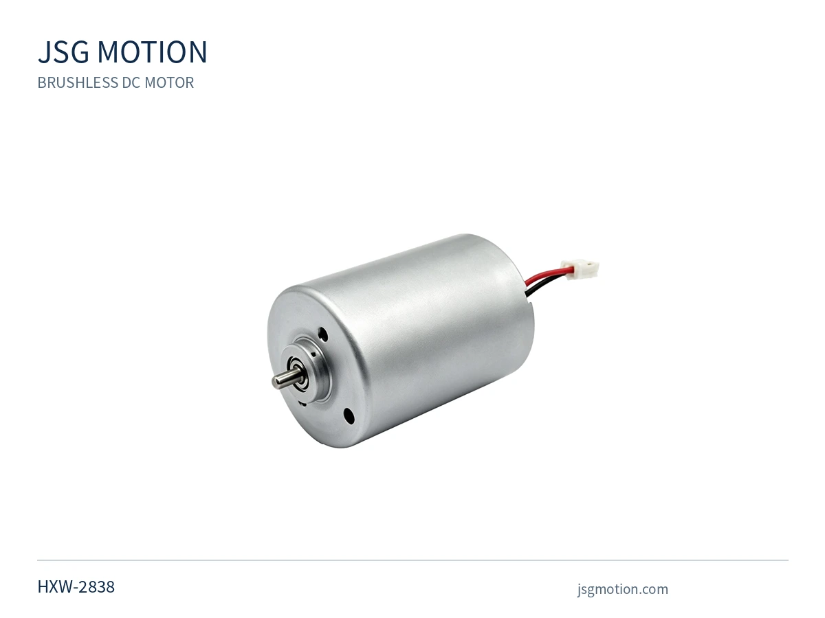
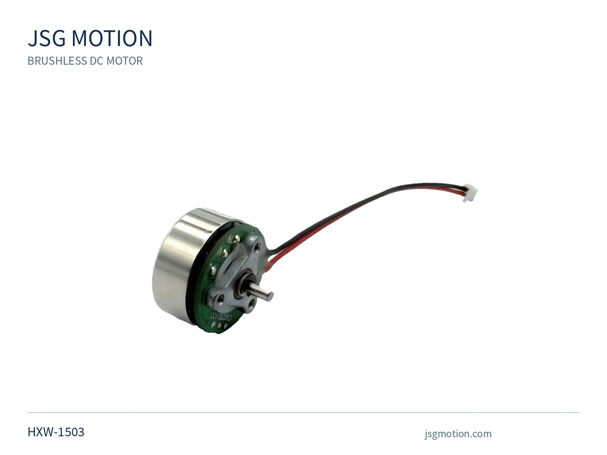
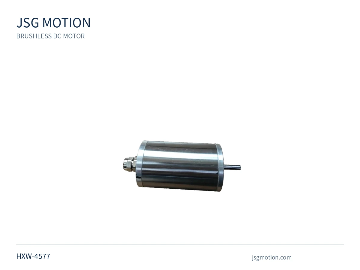
Supplied reference images · configuration data pending review.
Filters search published, verified motor data. Missing values never count as zero. Power filters use confirmed rated mechanical output only; source power with an unconfirmed definition is excluded. If your working point is not listed, request an engineering review.
START WITH YOUR REQUIREMENT
Share the information you have. We can review the operating point and the details needed for a suitable motor configuration.
Request motor selectionUNDERSTAND THE PLATFORMS
Define supply voltage, speed at load, torque and operating cycle for your equipment.
Explore motor typeReview the motor, driver, feedback and control interfaces as one integrated requirement.
Explore motor typeExplore coreless construction with the commutation type, load and mechanical envelope clearly specified.
Explore motor typeCommutation and construction are recorded separately so a coreless motor can also be identified as brushed or brushless.
WHAT TO CHECK
A speed value, torque value or size limit becomes useful when its operating condition is clear.
LET’S REVIEW YOUR APPLICATION
Send your voltage, speed, load torque, mechanical envelope and application details.